|
Fibre ChannelFibre channel, also written, fc is a technology that defines how data should be transmitted serially over copper and fiber optic media, fast and with low latency, from one node to another. Like any communications protocol, this one also uses a layered architecture. In this section we will discuss this technology and everything that combines this technology such as ports, topologies, media and layers. Where did it all start? It all started in the late 80's when a replacement for a technology called, HIPPI(High Performance Parallel Interface). HIPPI was mostly used on high end systems such as main frames for high speed data transfers. One of the problems with HIPPI was that it used big bulky cables that were prone to errors. It was also not really be used on mainstream systems because of this. With fibre channel, you could either use, copper wire or fiber optic media. This made it easier to implement this new technology on mainstream systems. It became very popular and is widely used today on smaller and higher end systems.
There are a couple of basic components that make up fibre channel. I've listed a few below. Fibre channel Host Bus Adapters(HBA) and World Wide Names(WWN) Fibre channel Switches Before we delve a bit deeper into fibre channel, let's first have a look at the different storage topologies we get. These define how system are connected to the storage. This could include FC, scsi, sas, sata etc. To understand Fibre channel, it's always a good idea to see how the storage is connected to hosts. The three most common topologies include, DAS (Direct Attached Storage), NAS (Network Attached Storage) and SAN (Storage Area Networks). Some also see iSCSI as a storage topology. In my view it's the same as NAS. The only difference is that with iSCSI, the storage is presented as disks over ethernet and with NAS it's a file centric model, so file systems are shared. DAS or Direct Attached Storage With this topology, the storage is directly connected to the servers. The client systems then connect to the storage systems via local area network and accesses the data through a client server application. This topology is the most common and companies still use it today. Below is a diagram to illustrate the DAS topology. 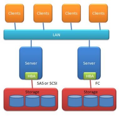 Connecting your storage directly is cheap and easy and no special hardware is needed to do this. The problem here is that you are limited in how much storage you can connect to the servers. You are basically limited to the number of expansion slots on the server. Another problem is that the sharing capabilities of the storage is limited to the server itself and the operating system you run on it. This topology also makes administration difficult. You could have multiple servers with different operating systems and multiple vendors storage products connected. You need someone to administrate all of this. This could be a potential headache. This setup, however, is preferred in small environments where the complexities of fibre channel switches are not needed. Lot's of people still use it and some even use it in mid size environments. NAS or Network Attached Storage Network attached Storage or NAS is where a device called a storage appliance or NAS appliance is used to connect storage over IP network. So, the server and storage is integrated in one device, called the NAS appliance. This is what is called a file centric model cause the appliance makes use of NFS (Network File System) or CIFS (Common Internet File System) to share file systems over the network to servers or clients. 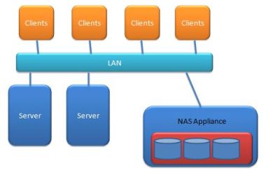 You basically have the storage and server integrated into one unit that shares file systems to servers and client computers. The NAS topology is very popular and a company called NetApp, specializes in this kind of storage. Oracle also recently introduced the 7000 series Unified storage range, that is based on ZFS (Zetabyte File System). With NAS you can use NFS, CIFS, iSCSI and Fibre Channel to present storage to computers. This makes NAS a very attractive option in any environment. Some people argue that you still use ethernet or IP networks to make the storage available to servers, and that this is not a good idea because of the overhead that is imposed on network packets. This might be true some years ago, but with today's 10Gbit networks, it's not the case anymore. You could create a separate network that is dedicated to the use of NAS. You could also optimize this network using jumbo frames on the hosts. SAN or Storage Area Networks At the heart of SAN technology are fibre channel switches. The storage does not directly connect to any servers but are connected via switches. You create your luns or volumes on the storage and these are then presented to hosts via fibre channel switches. The nice thing here is that the storage is managed separately from the servers. You can also use zones on the switches and lun masking on the storage devices for added security. 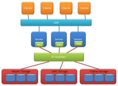 Another advantage is that you can connect storage from different vendors to the SAN and then use any piece of storage on different vendors servers. This makes it a truly heterogeneous environment. Scaling is also an advantage cause you are not limited to the number of slots like servers do. You can add more disks to the storage device or add more storage devices to the SAN. You can even connect switches together for bigger SAN environments. These SAN environments used to be quite expensive, but in recent years the price of this equipment has come down. It's still more expensive than DAS and NAS environments, but more affordable now. Another drawback is management. The diagram above only shows an example of a small environment. If you connect fibre channel switches together in core and edge configurations, this can become very complex. So, managing it can be a headache. SAN environments is preferred in mid to enterprise environments. Fibre Channel TopologiesFibre channel topologies depicts how nodes or devices are connecting together. These include Point-to-Point, Arbitrated loop and Fabric. Fibre channel transmits data serially, this means bit by bit. That's why the cabling only consists of a transmit port and a receive port. When you look at a physical fiber optic cable you will notice that there's only two connectors per side. A transmit (TX) and a receive (RX). Below is a picture showing this. 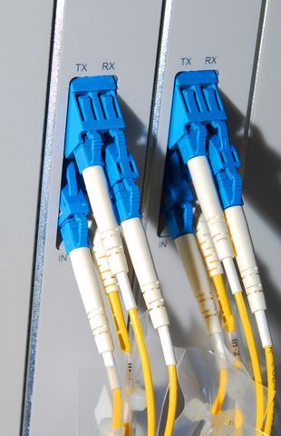 We will look at the different types of fiber cables a bit later. For now, knowing about the TX and RX ports will help us understand the topologies better. So, let's have a look at the Fibre channel topologies in more detail. Point-to-Point Point-to-Point is simplest of the fibre channel topologies. It just connects the two nodes TX and RX ports together. There's no loop or switch between the two devices. 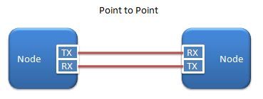 Fibre Channel Arbitrated Loop Also referred to as, fc-al (fibre channel arbitrated loop). People believe that this topology is the more complex of the three. I don't know if it's complex, I just know that compared to Fabric, it's slow. With Arbitrated loop the devices are connected together in a loop configuration. The TX port of the one device connects to the RX of the other, and so on. This forms a loop of devices that arbitrates for control of the loop in order to transmit data from one node to another. 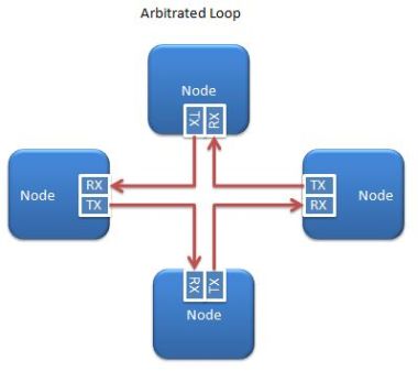 Keep in mind that the above picture is only a logical representation of the loop. Physically, both TX and RX ports are connected to the devices. With Fibre channel arbitrated loop, you don't connect individual devices together. You usually have a storage device with disks inside that connects like this. The devices communicated with each other via a AL_PA or Arbitrated Loop Physical Address. These AL_PA's are dynamically assigned when the loop powers up, or when nodes are added or removed while the loop is powered on. Some vendors uses fixed AL_PA's depending on the storage device. This process is called LIP or Loop Initialization Primitive. The entire loop is suspended while the LIP process is running. There are 127 possible AL_PA addresses (one byte) available for use. This means that a maximum of 127 devices can be connected in this topology. The AL_PA's is a by product of the 8 bit to 10 bit encoding from FC layer 1 or FC-1. The 127 addresses are from the neutral running disparity. The bandwidth is also shared among all the devices in the loop. As you can see, the more devices on the loop the slower it gets. For a device to communicate on the loop it needs an ALP_PA. After LIP has run, each device gets and AL_PA. If a device wants to take control of the loop, it transmits an ARBx frame, where the x is substituted with the AL_PA of the sending device. If the device that sent the ARBx frame receives the frame again with it's own AL_PA still intact, it can take control of the loop. It then send an OPNx frame, where the x is substituted with the device it wants to communicate with. Once the device receives the OPN frame, the two devices transmits their data. These two devices will now take full control of the loop and start their exchange of data. Nothing else happens on the loop until they are finished. It can also happen that the device that sends the ARB frame never receives the frame with it's own AL_PA. In this case another device with a lower AL_PA has inserted it's AL_PA in the frame. In fc-al, the device with the lowest AL_PA has the highest priority. So, it's very possible that a device with a higher AL_PA will have to wait for lower AL_PA devices, before it can take control of the loop. "Not fair", you say, and indeed it's not. There is a safety feature built in called, the algorithm of fairness. This, unfortunately, is optional. I'm not very fond of this topology cause it's slow and you are limited to only 127 devices per loop. Luckily for us, this topology is very rare and has been replaced by switched fabric. Fabric This is by far the most widely used topology used today. Just about every data center in the world uses this topology. Here, the devices are connected through a switch. All the devices exchange data through the switches. 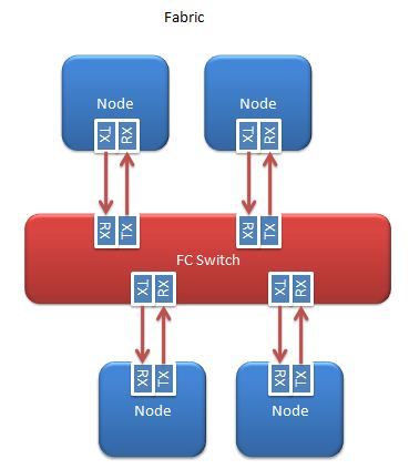 This topology does not use AL_PA's and the devices are not connected in a loop configuration. The devices connect in a point to point fashion to the switches. With switched fabric, each device that connects to the switch is assigned a 24 bit port address. This is 3 bytes. Each byte consists of 256 possible addresses starting from 00 to FF (hex) or 0 to 255 (decimal). Do the math, 3 bytes = 2 to the power of 24. This means that you can potentially connect up to 16 million devices to a single fabric. The first byte actually only goes up to 239 and not 256. The reason is that the fibre channel standards organization uses 16 of these addresses for it's own use. With fabric, there is no LIP process. Once you connect the device to the switch with a cable, it's assigned a port id which consists of 3 bytes. This information is kept on the switch which uses a simple name server. This is similar to DNS servers on IP networks. You can actually see this information once you logged into the switch. So, when a node sends a frame to another node, the frame hits the switch, the switch checks the frame for the destination id, finds in it's nameserver list and routes the frame directly to that port. This is called cut through routing. Much better than the lengthy ARB and OPN frames of Loop. This also has the advantage that each port will operate at the advertised speed. This is much more efficient than fc-al, that shares the speed of the loop between all connected devices. Fibre Channel PortsWith the Fibre channel topologies we looked at the different ways that nodes can connect to each other in order to exchange information. Let's now have a look at the different ports that you can set on a switch in order for these devices to communicate with each other correctly. Fibre channel ports basically tells the switch what types of devices is connected and how it should treat these devices that are logged in. For instance, you cannot have a loop only capable device connect to fabric only capable device. They don't speak the same language, so to speak. The loop capable device uses AL_PA's and the fabric device uses port id's. The addressing between the two devices are not the same. Lets have a look at the different ports. N_Port - Is a Node port. It could be a server or storage device. A N_Port means a single device, not more than one. On the switch itself, there is no N_Port. You would use a F_Port to configure N_Port devices to a switch. F_Port - Is a Fabric port. This port connects N_Ports to the switch. This port makes use of the 24bit port address. L_Port - Is a loop capable port. If the device is loop capable you would connect it as a L_Port. FL_Port - Is a fabric loop port. Ports with a L usually means that there are more than one device connected to the port. So, it's a single port, but there are multiple device behind that port or device. Storage devices such as the 3510 and 3511 from Sun Microsystems, could be configured as FL ports. You could also use this port with devices that are F capable. Sometimes people use FL instead of F if they have problems logging in with F. E_Port - Is a extension port. This port connects switches together. You would find the F_Port, FL_Port and E_Ports on today's switches. Below are some ports you might also encounter on switches. They are not as common. G_Port - Generic port. You might find this port on some Qlogic switches. Generic ports can reflect either F_Ports or E_Ports, It depends whether the device is a N_Port or another switch. GL_Port - Generic Loop Port. This port type can reflect a F_Port, E_Port or FL_Port. It all depends what is connected to the switch. Below is a list of legacy ports that Sun Microsystems used on the QLogic switches they use to sell. These are very old but I include them for reference purposes. SL_Port - Segmented loop port. These ports used to connect pure fc-al devices to a switch such as the A5200 Sun Enterprise Network Array's TL_Port - Translated Loop port. These ports were special ports that allowed the legacy T3A storage to be used with F_Ports on a switch. T_Port - Trunk ports. Before the E_Ports Sun used these ports to connect switches together. These ports were unlicensed, and you could use as many as you like. I've listed quite a few ports here, but the F_Port, FL_Port and E_Ports are the most common today. Below is a diagram that shows how these ports could be used to connect devices to a switch. 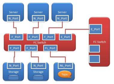 Fibre Channel LayersIt's always a good idea to look at the layers of a communications protocol to understand it a bit better. Let's have a look at the different layers that fibre channel is made up of. Fibre channel consists of 5 layers. FC-0 - Physical layer. Cables, transmitters, speed etc. FC-1 - Transmission protocol. 8bit to 10bit encoding. FC-2 - Signaling protocol. Ordered sets, frames, flow control, classes of service. FC-3 - Common services such as striping and multicast. FC-4 - ULP or upper layer protocol. Basically the application layer. SCSI, IP, IPI, HIPPI etc. Below is a diagram to better explain the layers. 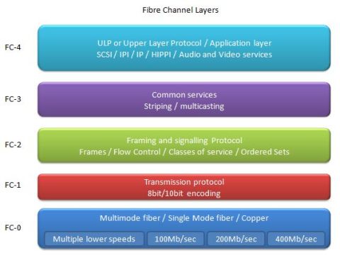 Let's look at each of these in a little more detail. This layer defines the physical interface and media. Things like fiber optic cables, speed and BER (Bit Error Rate). Speeds can range from 100Mb/sec or 1Gbit/sec to 800Mb/sec or 8Gbit/sec. Faster speeds are already in development. It's amazing to think that these speeds are possible with a serial communications protocol like fibre channel. Just imagine, 8 billion bits per second clocked from a single wire. That's amazing, and that's not even full duplex! With full duplex you can achieve 1.6Gbytes a second. It boggles the mind. Below is a picture of a typical fiber optic cable. 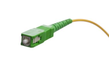 These fiber optic cables uses light instead of electrical voltages such as copper media. The advantage of light is that it's fast and can travel long distances. Just look at the stars at night. Some of those stars light has traveled billions of kilometers to reach us, so to speak. There is also little interference as light travels through these optic cables. That's why we can go longer distances. With long wave laser and single mode fiber, for instance, we can go up to 10Km. With shortwave laser and multi mode optic cables we can go up to 500meters. This is true for 100Mb speeds, as the speed increases these distances get shorter. Fiber optic cables overcomes a lot of the problems associated with copper cables such as signal interference. Unfortunately fiber optic cables are more expensive than copper cables. Let's get back to the multi mode and single mode fiber optics. With multi mode fiber, you get multiple wavelengths of light traveling through the core. The core is the glass where the light travels through. Multi mode fiber is cheaper to produce and the core is also thicker. The core ranges from 50-100 microns. The most common is 62.5micron. Because of the different wavelengths of light in the core, the signal could become fuzzy or distorted at some stage. The distance light can travel through multi mode is about 500 meters at 100Mb per second. With single mode fiber, the core is much smaller. It's about 9 micron. There is also only one wavelength of light that travels through the core. With single mode fiber optics cables you are looking at 10 Km at 100Mb second. Below is a diagram showing the different cables. 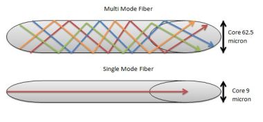 FC-1 - Transmission protocol. 8bit/10bit encoding So, what's with this 8bit/10bit encoding? Let's look at how SCSI (Small Computer System Interface) transfers data from one device to another. I will use a diagram to illustrate this.  Imagine that the above diagram is two electrical wires that runs from one device to another. A one, is represented by an electrical charge on the wire. A zero, is no electrical charge. That's easy enough but how does the end device actually know when to clock a bit from the wire? The answer lies in a line called the strobe. When the sending device sends a byte of data, it also send a small electrical current on the strobe line. This tells the receiving device to read the voltage on the data line. If there is a voltage, it's a one. If there is no voltage, it's a zero. Simple as that. In the above diagram the bits received would be, 0 1 0 0 1 0 1 1 0 1 0. Even if a series of 0's or ones is sent, the strobe will just tell the end device to read the voltage. It's like a CPU's clock. Now, let me change the above diagram slightly, and omit the strobe line.  What you see here is typically what happens on a fiber optic link. Remember, fibre channel is a serial protocol. You have one line for transmit (TX) and one line for receive (RX). There is no strobe line to tell the end device when to read the voltage of the line. In fact, there is no voltage. With fiber optic it's light that shines through the cable. In the above diagram, the sending device has sent a byte or two with zero's. Remember, a byte can be from 00 to FF in hex, 0 to 255 in decimal and 0000 0000 to 1111 1111 in binary. So it's very possible that a series of zero's (0x00) or one's (0xFF) could be sent. So, what do we do. How do we build the clock or strobe into the data transmitted?. For SCSI, it's not a problem. It just uses the strobe line. I have redrawn the diagram to show you how SCSI would handle it.  If you look at the diagram just count the triangles on the strobe line to see how many 0's were sent. In the example it's 9 zero's (0 0 0 0 0 0 0 0 0). Simple enough. So what about fibre channel? The answer lies in 8bit to 10bit encoding. Fibre channel sends data as a series of light signals through the fiber optic cable. A hex 00 would be a sustained negative voltage or no light and hex FF would be a sustained positive voltage or light on the optic cable. Unfortunately, the clock will get confused as to how many 1's or zero's it has received. Remember, the clock runs at over 1 billion times a second. It's bound to make a mistake. With 8bit to 10bit encoding, the normal 8 bits that's sent is converted to 10bits with some rules applied. Here are the rules: In a series of 20bits, the difference between 1s and 0s will not be more than 2. For example, you may have ten 1's and ten 0's or eleven 1's and nine 0's or eleven 0's and nine 1's. In a series of bits there will not be more than 4 bits of the same type in a sequence or in a row. For example, you may get 0 1 0 0 0 0 1 0 1 1. The number of 1's or 0's will not exceed 5. If you do get a sequence with 5 1's or 0's, then it will be some kind of control character such as K28.5. The encoder coverts 8bits to 10bits. There are 256 data characters called Dx.y and 12 control characters called Kx.y. 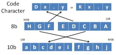 The encoder takes the original 8bit byte and divides it into 2 blocks, 3 most significant bits (MSB) y, and 5 least significant bits (LSB) x. The 3bit block is encoded to 4 bits and the 5bit block is encoded to 6 bits. These are then combined to form the new 10bit encoded value that is sent over the fiber optic cable to the other device as shown in the above diagram. For example, hex 0x00, binary 0000 0000 is D0.0 and the encoded value is 1011 100111. So 0000 0000 is actually sent over the fiber as 1011 100111. This is all done just to reset the clock, so that the data is sent correctly from one device to the other. Amazing! Below is a table that shows some of these conversions. It would be impractical of me to include all 256 characters in the table so I just show you some of them.
. .
You will notice from the table that there is actually 2 values for the encoded 8bits. The two values is called the running disparity or RD. For every encoded value there is a opposite value. If there is more 1's than 0's, then it's called positive running disparity. If there is more 0's than 1's, then it's negative running disparity. If you have the same number of 1's and 0's, it's neutral disparity. When the encoded values are sent, it will alternate between positive and negative RD. Character codes The most common is the K28.5. This character is one of few that actually has 5 bits of the same type in sequence. This just tells the device that this is a control character and that something is going to happen that involves some change. It could be a start of frame, end of frame or idles. I hope the above explanation sheds a little more light on the 8bit to 10bit encoding scheme used by fibre channel. FC-2 - Signaling protocol. Ordered sets, frames, flow control, classes of service. This is the most involved layer of all. I will briefly try to explain what happens here. Ordered sets are just collections of encoded characters that are grouped in 4 to tell the FC device that a change is about to happen, and what the change will be. The ordered sets usually start with a K28.5, and followed by 3 more characters. Frames are like packets in ethernet. The data that is sent over the fiber optic cable is put in a frame. Below is a diagram of the layout of a frame. 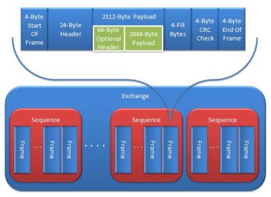 The first 4 bytes signals the start of a frame. These 4 bytes typically forms part of an ordered set. The fist byte would be a K28.5, the next 3 bytes would then be an indicator as to what type of control frame this is. The next 24bytes is the frame header. Information in the frame header includes, source id (S_ID), destination id (D_ID), sequence count, sequence id, exchange id, type of frame and so on. The header basically identifies what the frame is and where it's going. World Wide Names (WWN)It's worth mentioning the WWN or World Wide Name in a bit more detail here. The source id (S_ID) and destination id (D_ID) in the frame consists of the port addresses and not the WWN's. In ethernet packets, the MAC (Media Access Control) address is actually used as the source and destination id's.Some people then assume that it's the same in fibre channel frames. It's not. In fibre channel, the source and destination port id's are used in the frame header. So, what is a WWN and where does it come from? A WWN (World Wide Name) is the actual hardware address of the node. A node can be a port on a HBA (Host Bus Adapter) on a server or a port on a storage device or even a port on a disk or tape device. If a device is going to be connected to a fibre channel network, then it needs a WWN. In ethernet they use the MAC address. It's very similar. It's basically a hardware address, assigned to the device. Where does the WWN come from? An Organization called the IEEE (Institute of Electrical and Electronics Engineers) defines these addresses and assigns ranges to vendors who make fibre channel equipment. I'm not going into the intricacies of how they define the actual addresses, I'll just explain what they are. They are 64bits or 8 bytes in length. So, imagine if you have to cram this 64bit address into the 24byte header of the frame. This would mean that you only have 16bytes left to define the rest of the header. Switches are intelligent devices that keeps track of what is connected to it. When a device is connected to a FC switch, the device furnishes the switch with the details of it's capabilities. The WWN, of course, is also part of this information. The switch then builds a table of the devices that are connected such as the type of device, port address, WWN's and some other information such as credits etc. The frame need not include the WWN of the device, because this data is already captured when the device logs into the fabric. A port address is only 3 bytes or 24bits. That's much less than 64bits or 3bytes. This makes routing more efficient on the switch as well. Some vendors include more than one WWN for their devices. They are usually defined as a World Wide Port Name (WWPN) and a World Wide Node Name (WWNN). The WWPN is usually a port on the HBA or device and the WWNN is usually the adapter itself. Remember, the IEEE defines the ranges and how the WWN's are defined. The vendors can now go and rearrange, so to speak, the WWN's to easier identify their devices. The next 2048 bytes contains the data or payload. If it's a data frame then the data will typically be transferred in this section of the frame. If it's a SCSI command, then the command would be embedded in this section. Some people don't realize this, but there is also a 4 fill bytes after the payload. The payload must be multiples of four bytes. If the payload is not multiples of 4, then the 4 fill bytes is used as padding. Then there are 4 bytes for error checking and then the frame is closed with a 4byte end of frame. The frames are grouped into sequences and the sequences are then grouped into an exchange. This depends on the size of the data being sent to the node. Flow control is a mechanism that ensures guaranteed delivery of frames. You get buffer to buffer and end to end. Buffer to buffer is typically between a node and a switch port and end to end is between the nodes itself. This is done by a credit scheme. So the sending device, at fabric login, reports how many frames it can handle and the switch port reports how frame buffers it can handle. When the sending node sends a frame the buffer counter is decreased so that when it reaches it's limit, it would stop sending frames until it gets an acknowledgement. Below is a diagram to show the flow control. 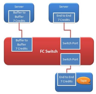 Classes of Service Classes of service defines how the data will be delivered to the end devices and should acknowledgement of frames be used or not. I will list the classes of service but will discuss class 1, 2 and 3 in a bit more detail. Class 1 - Acknowledged Connection Service What is the difference between connection orientated and connectionless? Connection orientated is like a telephone. When you phone someone, you and that person you talking to has complete access to the piece of wire and no one else can talk until you hang up. Connectionless is more like two way radio's. When you press the button you can speak. As soon as you release it someone else can interrupt and say whatever he likes. Class 1 is a connection orientated, acknowledged service. This means that the two devices establishes a connection through the switch and keeps the connection. This guarantees that the frames that are sent, are received by the receiving device and in the correct order. Class 1 is typically used in tape backup environments. This service also sends acknowledgements of frames to the sending device. Class 2 is a connectionless service but with acknowledgements of packets. The frame is sent to the receiving device and then before it gets to the application it acknowledges the frame. The application need not worry whether the frames were received or not, it's layer 4's job to do that. Class 3 is a connectionless unacknowledged service class. This sounds a bit bad, but most devices supports and uses this service. Great, but what happens if a frame gets corrupted along the way? Great question, it's actually the job of the application on layer 4 to check that the data has been received correctly. If not, then the application will ask for the frame to be resend. FC-3 - Common services such as striping and multicast. This layers basically include services for multiple ports on one node such as striping. It's still largely undefined, but as time goes by more of the features of this layer will be implemented.Apart from striping this layer also includes hunt groups and multicast. FC-4 - ULP or upper layer protocol. Basically the application layer. SCSI, IP, IPI, HIPPI etc. This is the highest level in the fibre channel hierarchy and it defines how the actual commands for the different protocols are embedded in the frame. The most common use of the ULP is SCSI. Instead of creating a whole new set of commands for fibre channel, the designers decided to use existing technologies like SCSI and IP to rather embed the SCSI commands in the frame and then send it to the device. This is quite clever cause this means that a lot of different technologies can be used on different devices. With earlier implementations of Sun Microsystems Qlogic switches, you could actually create a network interface on the server called fcip0 and use tcp/ip over fibre channel. Cool stuff! Last words I hope you have a bit better understanding of how fibre channel. It's quite a broad subject and I tried to cram as much as I can onto this page. I have given you some basic information which could help you in the future. If you want to delve deeper into fibre channel then I suggest you do some research on the net. There are lot's of documentation that you can have a look at.
Return from Fibre Channel to What is My Computer
|
Search what-is-my-computer.com

What is in my computer?
Discover what goes into a PC?


